Alpha 0.1.0
Create interactive 3D assembly guides, mockups and presentations - effortlessly.
What is VISIOLIX?
VISIOLOX is your all-in-one web toolkit for building interactive 3D construction manuals, mockups, and product presentations - directly in the browser. No coding. No software installation. Just upload your 3D models, define steps, group components, and even add animations to guide your users - whether you're designing DIY assembly / repair instructions, showcasing a product, planning a showroom, stage setup, you name it. Share your projects instantly online.
Quick Guide
Navigation
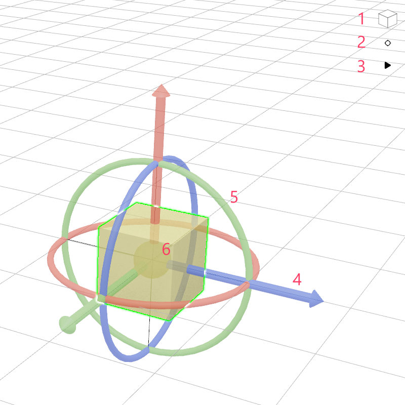
Use the Navigation Cube (1) in the 3D space menu to quickly switch views. Clicking one of the cube's planes will move the camera to the corresponding front, side, or top view. If no object is selected, the camera will focus on the origin.
The "Call Camera Position" (2) button returns the camera to the currently stored position and automatically adjusts the view to focus on the saved pivot point.
Use the "Pause / Play Animations" (3) button to pause or resume all animations in the scene.
When an object is selected, a 3D cursor appears at its origin. You can move the object by dragging the arrows (4), or rotate it by dragging the circular rotation handles (5). Use the yellow ball in the middle to freely move the object in any axis (6).
Step Controls
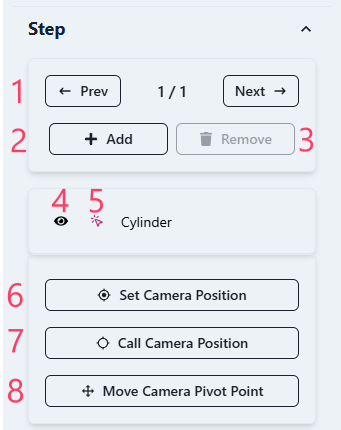
A step represents a chapter in your assembly guide or presentation. It can also serve as a variant of your mockup. You can navigate through the steps using the "Prev" and "Next" buttons (1). Add a new step with the "Add" button (2) - it will be inserted after the currently active step. Remove a step using the "Remove" button (3).
All configurations from the active step will be copied to the new one. If there are animations, the parts position will be where the previous step ends.
Below the step controls, you'll find the object list. It shows all objects in the scene. You can toggle the visibility of each object using the eye icon (4). Visibility changes are saved per step, meaning they only apply to the currently selected step.Use the arrow icon (5) to select an object. Alternatively, you can click directly on the object in the 3D view. Sometimes an object might be difficult to select in 3D space or may be hidden - selected objects are highlighted with a pink arrow icon.
The "Set Camera Position" button (6) stores the current camera position and angle for the current step. This configuration is also unique to each step. The "Call Camera Position" (7) button moves the camera back to the stored view.
With "Move Camera Pivot Point" (8), you can adjust the pivot point - this is the point around which the camera orbits in 3D space. Note that the pivot position and camera position are two independent settings.
Object Options
This section displays the properties of the currently selected object. It is only visible when an object is selected.
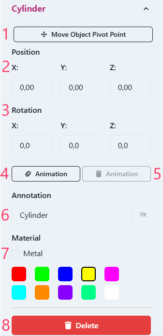
Use "Move Object Pivot Point" (1) to adjust the object's pivot (center). This is helpful if the pivot point is not positioned correctly after importing. The pivot defines the rotation center and where the 3D cursor appears.
Position (2) values define the object's location in the 3D space, while rotation (3) values define its orientation.
Clicking the "Animation" (4) button enables animation mode for the object. A green hollow duplicate will appear to represent the end position. You can adjust this end position and rotation in the same way as the original. Remove an animation with the trash icon (5).
The "Annotation" text (6) allows you to display a floating label attached to the object in the 3D space. Annotations are step-specific.
You can change the object's color under the "Material" section (7). Enable the "Metallic" option to give the object a metallic appearance.
To remove the object from the scene, click the "Delete" button (8).
Scene Settings
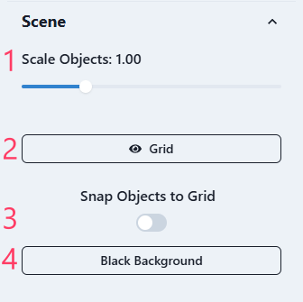
Depending on the input files, objects may appear too small or too large. Use the "Scale Objects" slider to adjust their overall scale.
You can toggle the visibility of the 3D grid using the "Grid" switch.
Enable "Snap Objects to Grid" to move objects in 1-unit increments when adjusting their position in the scene.
Use the "Background" button to toggle the background color between black and white.
Fasteners
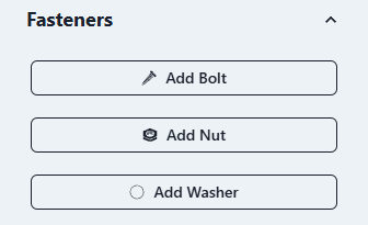
Quickly add bolts, nuts, and washers using the tools in the Fasteners section. The component library will be expanded with more options in future updates.
Groups
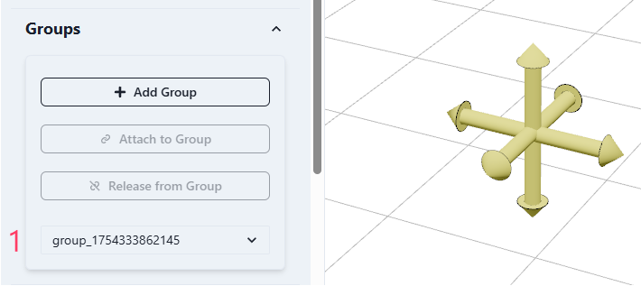
Groups allow you to attach multiple objects together so they can be moved or animated as one unit. Use the "Add Group" button to create a new group.
To attach an object to a group, first select the object in the scene or object list. Then choose the desired group from the dropdown (1) and click "Attach to Group".
To detach an object from a group, select it and click "Release from Group".
Grouping is step-specific: objects can be grouped in one step and separate in another. This allows for flexible configurations across steps.
Groups are represented as a yellow arrow icon in the 3D space.
Files
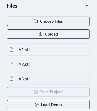
Choose files to upload into the scene using the "Choose Files" button. Currently supported formats are .stl, .gltf, .glb, and image files. Images will be imported as flat planes. You can select multiple files at once.
After selecting your files, click the "Upload" button to add them to the scene.
The "Save Project" button is not available in this alpha version, as individual user project management has not yet been implemented.
Click "Load Demo" to load a demo scene for testing or demonstration purposes.
Notes
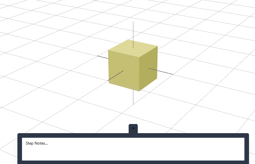
You can add individual notes for each step in this section. Notes are intended to describe or clarify the current step - for example, assembly instructions, technical explanations, or any other relevant information.
These notes are saved per step.
Newsletter
Stay up to date with the latest updates and news from VISIOLOX!
Roadmap
User Management System
Accounts, project sharing, visibility controls, and collaboration settings to enable structured teamwork and access control.
Incorporate Features from User Feedback
Continuous improvement through user-centered design, prioritizing popular requests and usability suggestions.
Multi-language Support
Introducing localization starting with German, with a scalable framework to support more languages over time.
Integration with CAD Systems
Direct import and linking with popular CAD platforms to streamline workflow and avoid redundant conversions.
Export to Standalone App
Allow users to package and distribute assembly instructions as standalone desktop or web apps.
Undo System
Step-by-step undo and redo functionality to enhance usability and reduce user errors during complex operations.
Raytraced Render Output
High-quality photorealistic rendering for documentation, marketing, and print output.
AI Model Generation
Leverage AI to generate instructional models or placeholders based on textual or structural input.
Configurable Fastener Library
Parametric library of screws, bolts, clips, and fasteners.
Continuous Improvements
Many more features and enhancements, from integration to the material library, lights support, workflow streamlining, nested assemblies, to overall UX/UI polish.
Terms and Conditions
Assembly Assistant Builder - Alpha Version
Last updated: 25.07.2025
1. Alpha Software Disclaimer
This is an alpha version of the Assembly Assistant Builder. Features are incomplete and under active development. The service is provided as-is without guarantees of availability, stability, or functionality.
2. Data Usage and Storage
- Projects cannot be saved or shared in this version.
- Uploaded data (3D models and images) is stored temporarily on the server only for the duration of your session and solely for processing purposes.
- Data is not persistently saved or backed up.
- When subscribing to the newsletter, your email address is stored locally and securely for the sole purpose of sending occasional updates.
- You can unsubscribe at any time via the link provided in each email, and your email address will then be permanently deleted.
- Your data will never be shared with third parties.
3. Logging and Activity Tracking
To improve the tool and monitor system health:
- A minimal, non-personalized activity log is maintained.
- No personally identifying information is collected at this stage.
4. Cookies and Tracking
- This version does not use cookies or third-party trackers.
- Any cookies potentially set by React or Chakra UI are limited to basic UI functionality and do not collect personal data.
5. Liability
Use of this software is at your own risk. The developer assumes no liability for data loss, service interruption, or other damages resulting from use of this tool.
6. Intellectual Property
All code, assets, and branding of VISIOLIX remain the intellectual property of SIMULUX unless otherwise stated.
7. Feedback
By using this alpha version, you're invited to submit feedback and feature requests. This helps guide development and improve the final product.
Any information you provide (email and name) will only be used for the purpose of soliciting feedback. You may be contacted by the development team in regards to your feedback. Your data will not be used for any other purpose or shared with any third party.
8. Privacy Policy
We value your privacy. Visiolix does not collect any personal data without your consent. Any information you provide is stored securely and used only for the purposes of improving our service or fulfilling your requests. No data is shared with third parties unless required by law. You have the right to access, correct, or delete your data at any time. For inquiries regarding data protection, please contact us directly.
9. Contact
All rights reserved © Simulux 2025.